

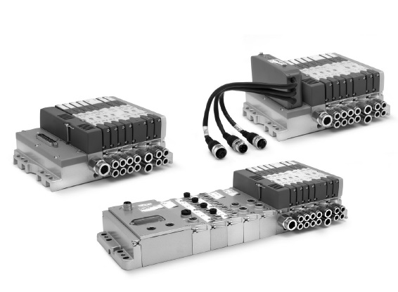
Multipole connection with 25 or 37 pins
GENERAL DATA
| PNEUMATIC SECTION | |
| Valve construction | spool with seals |
| Valve function | 5/2 monostable and bistable 5/3 CC 2 x 2/2 NO 2 x 2/2 NC 1 x 2/2 NC+ 1 x NO 2 x 3/2 NC 2 x 3/2 NO 1 x 3/2 NC+ 1 x 3/2 NO |
| Materials | spool in aluminium spool seals in HNBR other seals in NBR cartridges in brass body and end covers in technopolymer subbase in aluminium |
| Connections | Inlets 2 and 4, size 10,5 mm: M7, tube Ø 4, tube Ø 6 Inlets 2 and 4, size 21 mm: G1/8, tube Ø 6, tube Ø 8 Supply 1: G1/4, tube Ø 8, tube Ø 10 Supply 12/14: M7 Exhausts 3 and 5: G1/4 or with integrated silencer Exhausts 82/84: M7 |
| Temperature | 0 ÷ 50°C |
| Air specifications | Filtered compressed air, non lubricated, class 6.4.4 according to ISO 8573-1:2010. If lubrication is necessary, please only use oils with maximum viscosity of 32 Cst and the version with external servo-pilot supply. and the version with external servo-pilot supply. |
| Valve sizes | 10.5mm (2 valves for each subbase) 21mm (1 valve for each subbase) |
| Working pressure | - 0,9 ÷ 10 bar |
| PIlot pressure | 3 ÷ 7 bar 4.5 ÷ 7 bar (with working pressure exceeding 6 bar for the versions 2x2/2 and 2x3/2) |
| Flow rate | 400 Nl/min (10.5mm) 700 Nl/min (21mm) |
| Mounting position | any position |
| Protection class | IP 65 |
| ELECTRICAL SECTION - MULTIPOLE VERSION | |
| Type of Sub-D connector | 25 or 37 pins |
| Max. absorption | 0.8 A (with Sub-D connector 25 pins) 1 A (with Sub-D connector 37 pins) |
| Supply voltage | 24 V DC +/- 10% |
| Max. number of coils to operate | 24 on 20 valve positions (with Sub-D connector 25 pins) 32 on 28 valve positions (with Sub-D connector 37 pins) |
| Valve signalling | yellow led |
| ELECTRICAL SECTION - FIELDBUS VERSION | |
| General data | see the CX section (2.3.50) |
| Max. absorption | digital outputs / analog outputs and inputs 3A digital/analog inputs 3A |
| Supply voltage | logic supply 24 V DC +/- 10% power supply 24 V DC +/- 10% |
| Max. number of coils to operate | 32 on 28 valve positions |
| HN | SERIES | ||
| 5 | SIZE: 1 = 10.5 2 = 21 5 = MIxed |
||
| M | ELECTRICAL CONNECTION: M = Multipole 25 pin PNP N = Multipole 25 pin NPN H = Multipole 37 pin PNP L = Multipole 37 pin NPN |
||
| 03A | CONNECTION: 000 = without connector/cable CONNECTOR WITH CABLE AXIAL OUTPUT: 03A = 3m 05A = 5m 10A = 10m 15A = 15m 20A = 20m 25A = 25m CONNECTOR WITH RADIAL OUTPUT: 03R = 3m 05R = 5m 10R = 10m 15R = 15m 20R = 20m 25R = 25m CONNECTOR WITHOUT CABLE: 4XA = 25 pins axial 4XR = 25 pins radial 9XA = 37 pins axia 9XR = 37 pins radial |
||
| 2Q4AZ2A | SUBBASES FOR 2 SOLENOID VALVES SIZE 1 (*): A (AZ) = M7 threads B (BZ) = 4 fittings for tube Ø4 C (CZ) = 4 fittings for tube Ø6 D (DZ) = channel 1, 3, 5 closed; M7 threads E (EZ) = channel 1, 3, 5 closed; cartridges tube Ø4 F (FZ) = channel 1, 3, 5 closed; cartridges tube Ø6 G (GZ) = channel 3, 5 closed; M7 threads H (HZ) = channel 3, 5 closed; cartridges tube Ø4 I (IZ) = channel 3, 5 closed; cartridges tube Ø6 L (LZ) = channel 1 closed; M7 threads M (MZ) = channel 1 closed; cartridges tube Ø4 N (NZ) = channel 1 closed; cartridges tube Ø6 (*) Subbases with “Z” at the end of their code are used with monostable solenoid valves FOR SOLENOID VALVES SIZE 2: Q = G 1/8 threads R = cartridges for tube Ø6 S = cartridges for tube Ø8 |
SUBBASES FOR PNEUMATIC SUPPLY: X = supplementary supply and exhaust Y = supplementary supply and exhaust with integrated silencer W = supply from the exhausts FOR ELECTRICAL SUPPLY: K = separation of electrical supply |
SEALS T = diaphragm on channels 1, 3, 5 U = diaphragm on channel 1 V = diaphragm on channels 3, 5 |
| 2B8M4C | 2B8M4C Size 1 and 2: 0 = island without solenoid valves M = 5/2 Monostable B = 5/2 Bistable V = 5/3 Centres Closed C = 2 x 3/2 NC A = 2 x 3/2 NO G = 1 x 3/2 NC + 1 x 3/2 NO E = 2 x 2/2 NC F = 2 x 2/2 NO I = 1 x 2/2 NC + 1 x 2/2 NO L = free position |
SOLENOID VALVE + PRESSURE REGULATOR on channel 1 (size 2 only): N = 5/2 Monostable P = 5/2 Bistable Q = 5/3 Centres Closed R = 2 x 3/2 NC S = 2 x 3/2 NO T = 1 x 3/2 NC + 1 x 3/2 NO U = 2 x 2/2 NC X = 2 x 2/2 NO Y = 1 x 2/2 NC + 1 x 2/2 NO |
|
| A | THREADED TERMINAL PLATES: A = 1, 12/14 in common 3/5, 82/84 threaded ports B = 1, 12/14 separated 3/5, 82/84 threaded ports C = 1, 12/14 in common 3/5, 82/84 with integrated silencer D = 1, 12/14 separated 3/5, 82/84 with integrated silencer |
TERMINAL PLATES with FITTINGS FOR TUBE Ø 8 on PORT 1: E = 1, 12/14 in common 3/5, 82/84 conveyable F = 1, 12/14 separated 3/5, 82/84 conveyable G = 1, 12/14 in common 3/5, 82/84 with integrated silencer H = 1, 12/14 separated 3/5, 82/84 with integrated silencer |
TERMINAL PLATES with FITTINGS FOR TUBE Ø 10 on PORT 1: I = 1, 12/14 in common 3/5, 82/84 conveyable L = 1, 12/14 separated 3/5, 82/84 conveyable M = 1, 12/14 in common 3/5, 82/84 with integrated silencer N = 1, 12/14 separated 3/5, 82/84 with integrated silencer |