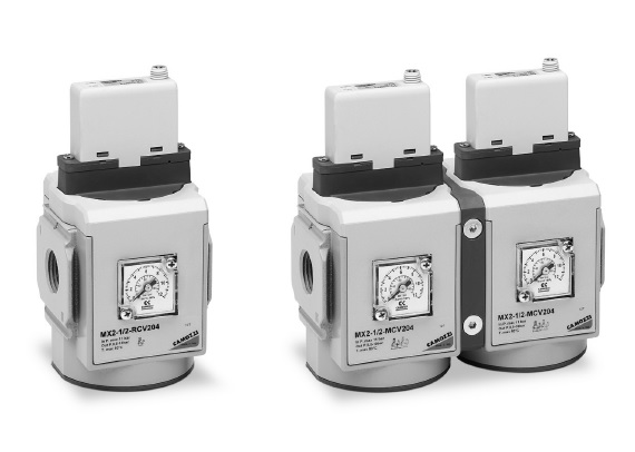
Ports: G1/2
General data:
| Construction | modular, compact, diaphragm type |
| Materials | see tables on the following pages |
| Ports | G1/2 |
| Mounting | vertical in-line, wall-mounting (by means of clamps) |
| Working temperature | 0°C ÷ 50°C |
| Max inlet pressure | 11 bar (10 bar), 4 bar (3 bar) |
| Regulated pressure | 0.5 ÷ 10 bar, 0.15 ÷ 3 bar |
| Overpressure exhaust | with relieving (standard) without relieving |
| Nominal flow | see flow diagrams (following pages) |
| Air specifications | Filtered compressed air, non lubricated, class 3.4.3 according to ISO 8573.1 standard. If lubrication is necessary, please use only oils with maximum viscosity of 32 Cst and the version with external servo-pilot supply. The servo-pilot supply air quality class must be 3.4.3 according to ISO 8573.1 standard. |
| Pressure gauge | version with built-in pressure gauge (standard) version with G1/8 port |
| Analogical input | 0-10 V DC Ripple ≤ 0.2% 4–20 mA |
| Analogical output | 0.5-9.5 V DC [ Feedback ] |
| Supply / consumption | 19-28 V DC - ~1 W |
| Linearity | ≤ ± 1% FS |
| Hysteresis | ±0.5% FS |
| Repeatability | ±0.5% FS |
| Sensibility | 0.3% FS |
| Protection class | IP51 |
| Electrical connection | M8 4 Pin (Male) |
| MX | SERIES |
| 2 | SIZE: 2 = G1/2 |
| 1/2 | PORTS: 1/2 = G1/2 |
| R | TYPE OF REGULATOR: R = pressure regulator M = Manifold pressure regulator (G1/2 only) |
| CV | COMMAND: CV = electrical command 0-10 V DC CA = electrical command 4-20 mA EV = electrical command 0-10 V DC with external servo pilot supply EA = electrical command 4-20 mA with external servo pilot supply |
| 2 | OPERATING PRESSURE (1 bar = 14.5 psi) 1 = 0.15 ÷ 3 bar 2 = 0.5 ÷ 10 bar (standard) |
| 0 | DESIGN TYPE: 0 = relieving (standard) 1 = without relieving |
| 4 | PRESSURE GAUGE: 0 = without pressure gauge (with threaded port for gauges) 2 = with built-in pressure gauge 0-6 and working pressure 0.15 ÷ 3 bar 4 = with built-in pressure gauge 0-12 and working pressure 0.5 ÷ 10 bar (standard) |
| LH | FLOW DIRECTION: = from left to right (standard) LH = from right to left |